C Language Raymarcher
Raymarching—like raytracing, involves the casting of 'rays' outward from a camera. Where these two techniques differ, however, is how geometry is represented and how intersections are calculated.
Signed Distance Fields
To render an object with raymarching, you must first obtain its mathematical representation as a signed distance field (SDF)—essentially, you must be able to give the distance to the object from any arbitrary input coordinate. This distance is essential to the idea of 'marching' a ray, since it can also be interpreted as the maximum distance the ray can travel with no likelyhood of intersecting scene geometry. It is intuitive, then, that one can repeatedly 'march' an individual ray by the distance given by the SDF until this distance is unreasonably small as a method to generate intersections. This is the basis of the relationship between signed distance fields and raymarching—for each ray that intersects with the scene, the corresponding pixel's colour is changed.
Creating Scenes
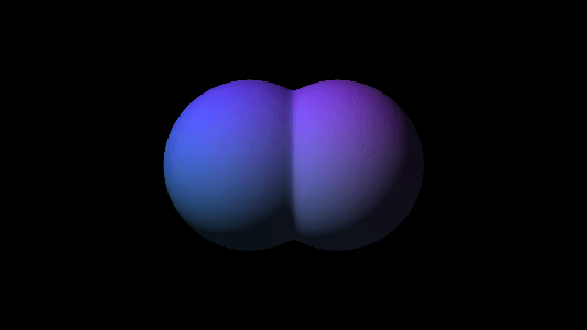
The difficulty of deriving the SDF for a shape sharply increases with its complexity, and so the key is to use simple geometry in coordination, that is, calculate the SDF of the union of two or more shapes. This can be done by taking the minimum of multiple distance functions, opening up the possibility for smooth transitions between shapes by using a "smooth" version of the traditional minimum function (Figure 1).
 Figure 1 - Two Spheres blended with a smooth min function
Shading and 3D Effects
For most applications, it isn't good enough to know only which pixels contain geometry—it is also important to know how to appropriately shade said geometry. This involves finding which direction a surface is facing, otherwise known as the surface normal. Since the normal is the direction that points most directly away from the surface, this can also be interpreted as the direction of which the SDF increases at the fastest rate. In calculus, this is called the gradient, and it is defined by the vector having components equal to the partial derivatives of the SDF with respect to each axis.
With the gradient in hand, it is possible to calculate diffuse shading. It is helpful—for reasons that will become apparent—to normalize both the gradient and the vector pointing from the light source to the surface. We can then calculate the negated dot product of these normalized vectors where \(\vec{g}\) is the gradient and \(\vec{l}\) is the light vector,
$$-(\vec{g} \cdot \vec{l}) = -|\vec{g}||\vec{l}|cos(\theta) = -cos(\theta),$$ and \(|\vec{g}||\vec{l}| = 1\) because they are normalized. From here it is rather intuitive that the cosine of the angle between our vectors impacts the amount of diffuse light hitting the camera, as it is maximal when the vectors are in-line and reduced when the vectors are orthogonal or facing away from eachother. For this reason it becomes necessary to negate our result, as the surface should be brightest when the surface normal is pointing opposite to the light vector.
It is also necessary to clamp the output, so that no negative values are produced. For realism, one may also chose to add ambient lighting, so that our revised pixel brightness expression becomes
$$\max(-(\vec{g} \cdot \vec{l}), 0) \cdot (1 - a) + a,$$ where \(a\) is the proportion of ambient light in the scene.
Domain Repetition
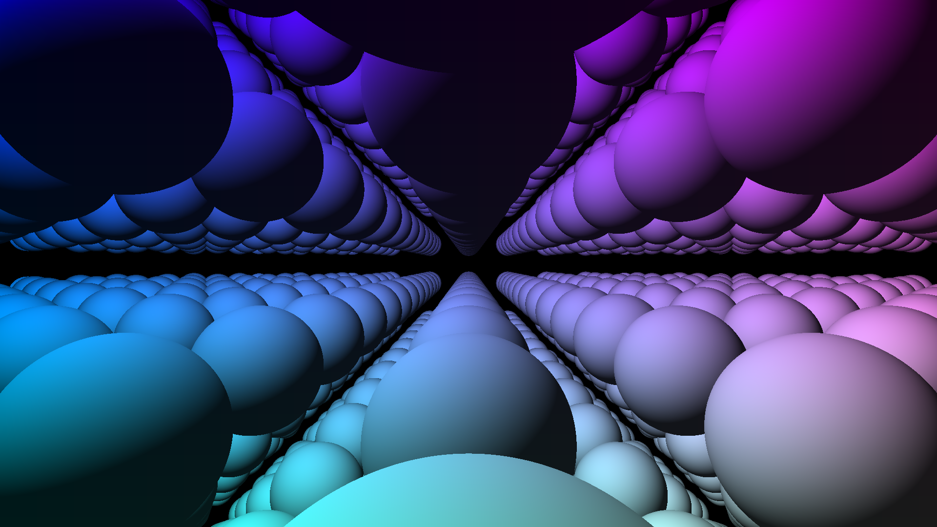
The advantages of directly simulating rays manifest in many different ways, almost all of which being 'free' or 'bonus' rendering effects that would be more computationally expensive when implemented in other rendering environments. One such advantage for raymarching is domain repetition, where an infinite number of surfaces can be rendered at the price of one. This is accomplished by 'wrapping' light such that space becomes toroidal, that is, compute the position of a ray as the modulus of its position over a certain domain length in all three dimensions. (Figure 2).
 Figure 2 - Domain Repetition
Personal Conclusion
This project was very daunting in the sense that it was complex mathematically as well as being difficult to design and program. I drew a lot of inspiration and learning from Inigo Quilez, who has written much more comprehensive articles on his blog. His videos are both informative and inspiring, and it is mostly because of his content that I decided to pursue this project.
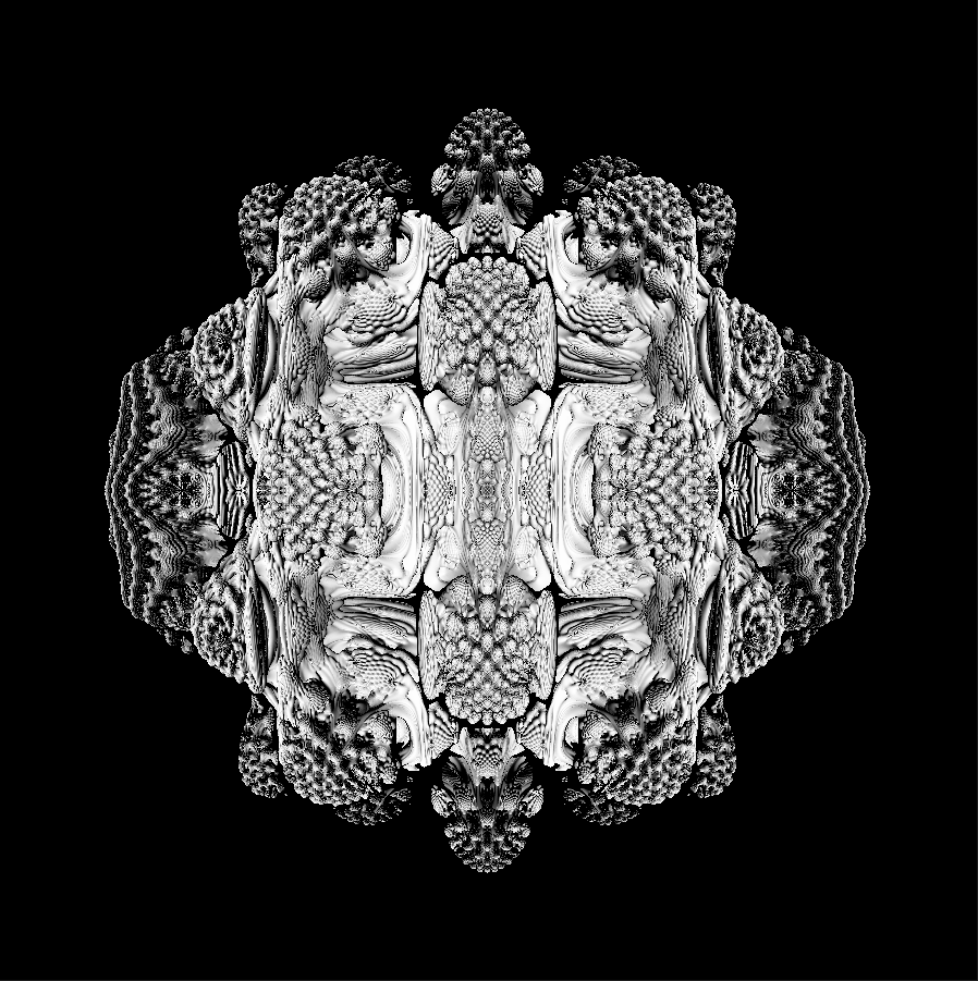
The most rewarding part of any creation is when you find unique and awesome applications that were not personally considered previously. This moment for me was when I researched and found the SDF for a 3D fractal called the Mandelbulb, which I subsequently rendered (Figure 3).
 Figure 3 - The Mandelbulb fractal
This idea was by no means novel, but it was an inspiring display of the power of mathematics and computer science. In the future, I plan to implement many more projects like this.